First Build Day of the Year
It was great to see everyone and great to see the hardware again. In the time that's elapsed since any fabrication efforts, a number of refinements have been identified.
One of the most important solutions involved the redesign of the two valves and one actuator piston which release the kerosene and liquid oxygen for launch.
The valve, which is a modification of two stainless steel ball valves bought off McMaster Carr, was designed off our old valve, which worked perfectly at room temperature, but froze up and failed to acctuate when tested with liquid nitrogen. The fix - which included better machining - substituted the 1 inch diameter piston for a 1.5 inch diameter piston, while also allowing for us to deliver a higher actuation pressure – meaning that the valve levers will receive a much greater force, and hopefully open much more reliably.
After many conversations, we have realized that this valve design will always be inferior to a truly cryogenically designed valve - The only stumbling point being that we can't afford one. We hope to incorporate cryo-friendly valves into our Static Fire System refurbishment, and hopefully in future rockets.
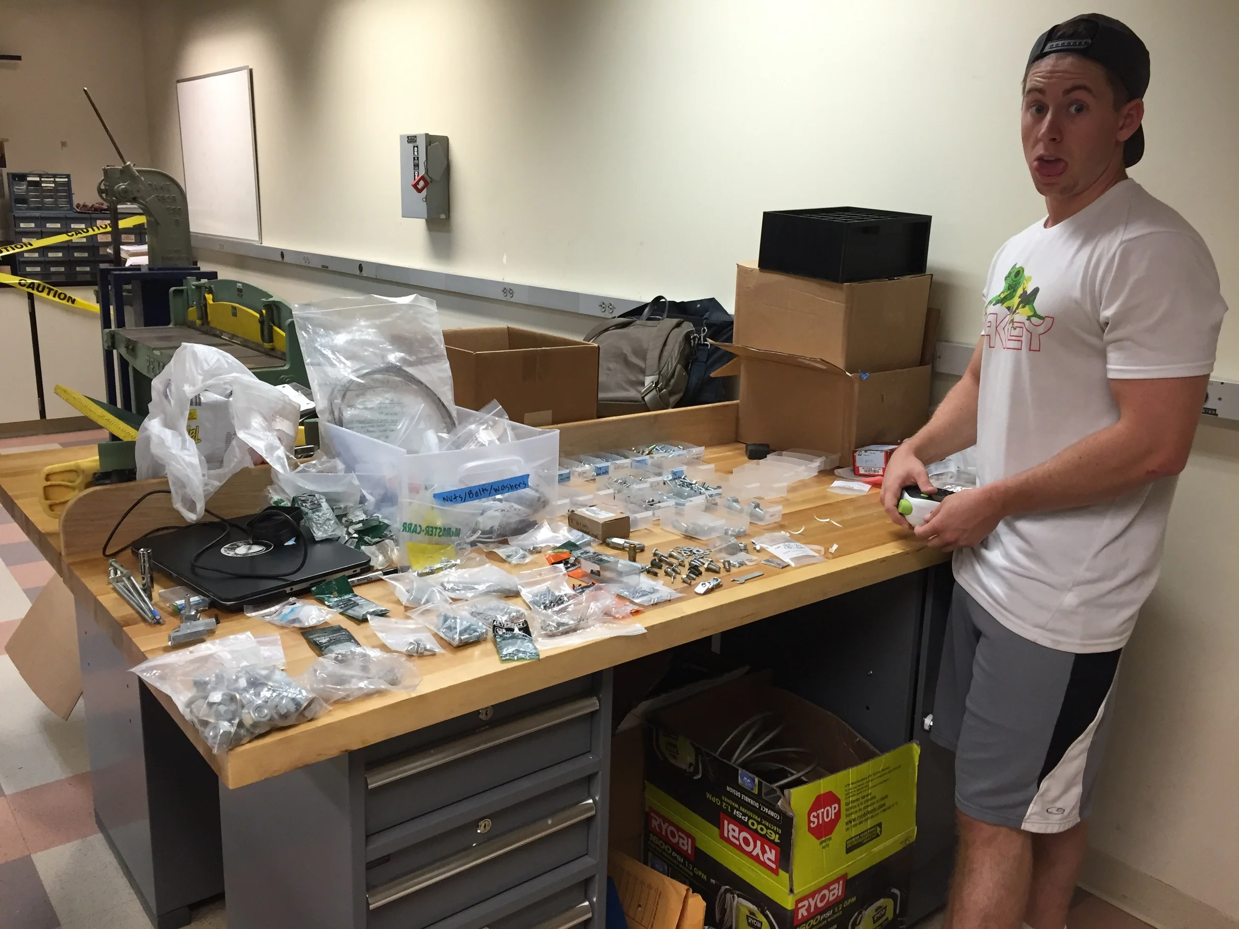
And of course, lots of hardware sorting.
In addition to the valve switch up, the dewar that we fill our oxygen and nitrogen from will be higher pressure, meaning that the dribble that was causing us problems previously will hopefully be increased to a more reasonable fill rate.
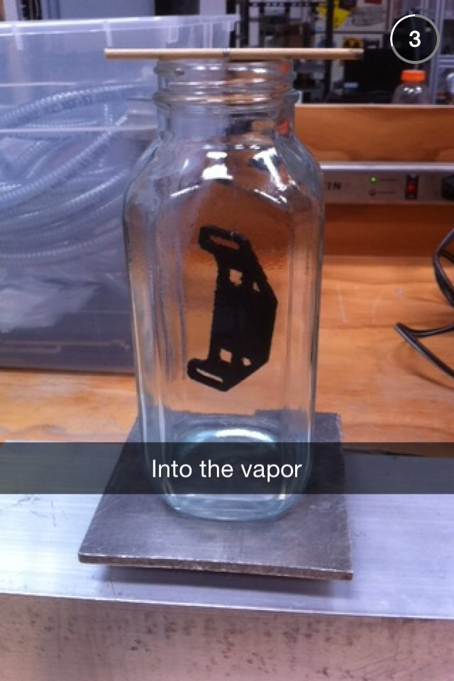
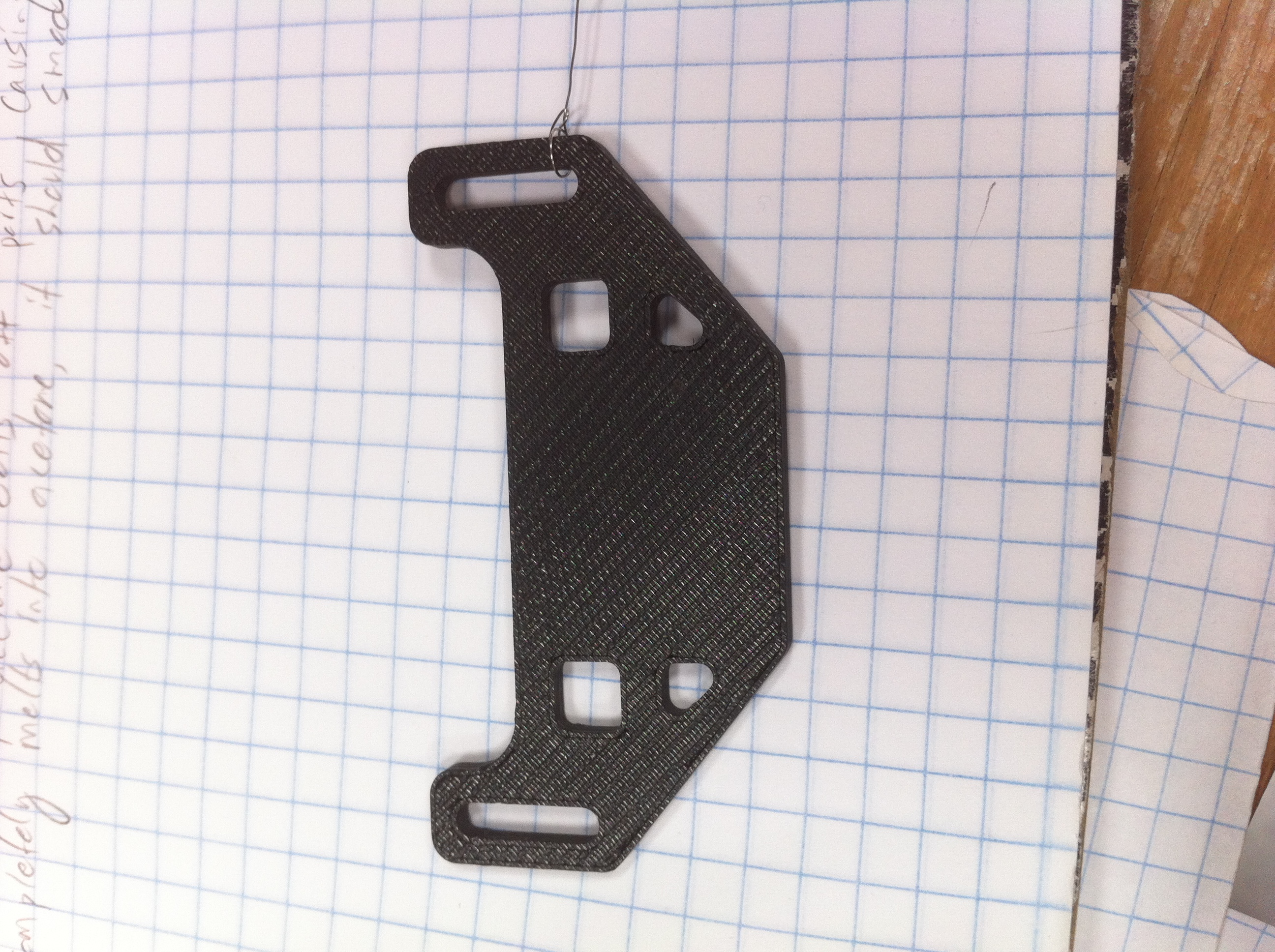
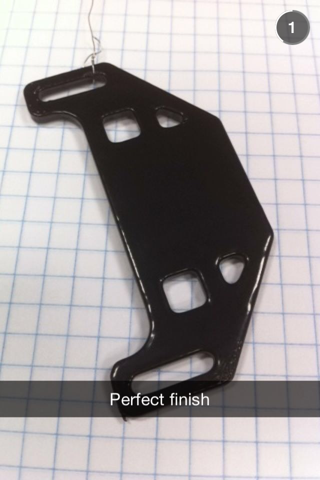
Finally, the composite aerodynamic structures will be receiving a refinishing, and all logos of our beloved sponsors will be bestowed on the rocket with vinyl stickers.